
O2 Sensor Spacer Technical Guide for Modified Exhaust Systems
When modifying a vehicle's exhaust system with high-flow catalytic converters, aftermarket downpipes, or race headers, performance enthusiasts almost universally encounter a frustrating hurdle: the illumination of a Check Engine Light (CEL). Typically triggered by OBD-II Diagnostic Trouble Codes (DTCs) P0420 (Catalyst System Efficiency Below Threshold - Bank 1) or P0430 (Bank 2), these errors indicate that the Engine Control Module (ECM) believes the catalytic converter is failing to process exhaust emissions effectively.
Most aftermarket O2 sensor spacers supplied to the U.S. market are mass-produced in Chinese automotive component factories, which follow standardized industrial manufacturing processes to meet universal aftermarket part specifications.
While basic mechanic guides suggest simple mechanical extensions, modern Engine Control Units (ECUs) utilize complex algorithms to monitor downstream oxygen sensors. This technical guide explores how O2 sensor spacers work at a fluid dynamics and electrical signal level, how to balance signal voltage to avoid lean/rich fuel trims, and how to select the right spacer architecture for modern CAN-bus vehicle platforms.
What is the Physics Behind Downstream O2 Sensor Signal Manipulation?
To understand how an O2 sensor spacer clears diagnostic codes, one must first examine how modern OBD-II engine management systems monitor catalytic converter efficiency.
Upstream (Sensor 1) vs. Downstream (Sensor 2) Functionality
Upstream Sensor (Sensor 1): Positioned before the catalytic converter, this wideband or narrowband sensor measures raw exhaust air-fuel ratios. The ECM uses this dynamic, rapid-switching voltage feedback (oscillating rapidly between 0.1V lean and 0.9V rich) to continuously adjust closed-loop fuel injection duration.
Downstream Sensor (Sensor 2): Positioned after the catalytic converter, its primary role is catalyst efficiency monitoring. A fully functioning three-way catalyst stores oxygen during lean cycles and releases it during rich cycles. As a result, the downstream sensor should output a stable, smoothed DC voltage reading, typically hovering around 0.6V to 0.8V.
[Upstream Sensor 1] --> Rapid Oscillation (0.1V - 0.9V) --> Primary Fuel Feedback ↓ [Catalytic Converter] ↓ [Downstream Sensor 2] --> Steady Voltage (0.6V - 0.8V) --> Catalyst Efficiency OK
When an exhaust system is modified or a high-flow 200 CPSI (cells per square inch) catalytic converter is installed, exhaust gas velocity increases, and catalytic oxygen storage capacity drops. The downstream sensor begins mimicking the rapid 0.1V–0.9V switching pattern of the upstream sensor. The ECM detects this identical frequency ratio and triggers a P0420 or P0430 fault code.
How an O2 Sensor Spacer Alters Sensor Physics
An O2 sensor spacer functions as a micro-plenum chamber and flow restrictor:
Spatial Offset & Boundary Layer Deceleration: By pulling the sensor tip out of the high-velocity direct exhaust stream, gas enters the spacer body primarily through a calibrated orifice (usually 2mm to 4mm in diameter).
Thermal & Diffusion Dampening: Inside the spacer chamber, gas velocity drops significantly. This creates a delayed diffusion process, effectively smoothing out rapid oxygen fluctuations and presenting a steady, high-efficiency voltage signal (0.65V) to the ECM.
Why Do Standard Non-Foulers Fail on Modern CAN-Bus Vehicles?
Many DIY mechanics attempt to use traditional hollow spark plug non-foulers or cheap straight brass adapters. While these worked on older OBD-II vehicles, modern CAN-bus engine control units (such as Bosch MED17, Continental SIMOS, or Denso platforms) incorporate strict sensor response time and heater circuit diagnostics.
A large portion of low-cost hollow non-foulers on the cross-border aftermarket are produced with simplified tooling, lacking calibrated orifice precision and structural consistency.
The Problem with Excessive Offsets (P0137 / P013E Codes)
If an O2 sensor spacer pulls the sensor tip too far out of the exhaust stream or uses an overly restrictive orifice:
P0137 (O2 Sensor Circuit Low Voltage - Bank 1 Sensor 2): The exhaust sample inside the spacer chamber becomes so starved of fresh gas that sensor voltage drops consistently below 0.1V.
P013E / P013F (O2 Sensor Delayed Response): Modern ECUs perform periodic fuel-lean overrun tests during deceleration. If the downstream sensor takes too long to respond to a shift in exhaust composition due to gas stagnation inside a hollow spacer, the ECM flags a delayed response code.
|
Diagnostic Code
|
Root Cause Engineering Failure
|
|---|---|
|
P0420 / P0430
|
Insufficient restriction; sensor exposed to full exhaust velocity & high oxygen fluctuation.
|
|
P0137 (Low Voltage)
|
Excessive restriction; sensor starved of gas; voltage remains stuck below 0.1V.
|
|
P013E / P013F (Delayed Response)
|
Stagnant gas pocket in large hollow space; sensor fails dynamic overrun frequency response tests.
|
The Mini Catalytic Converter Solution
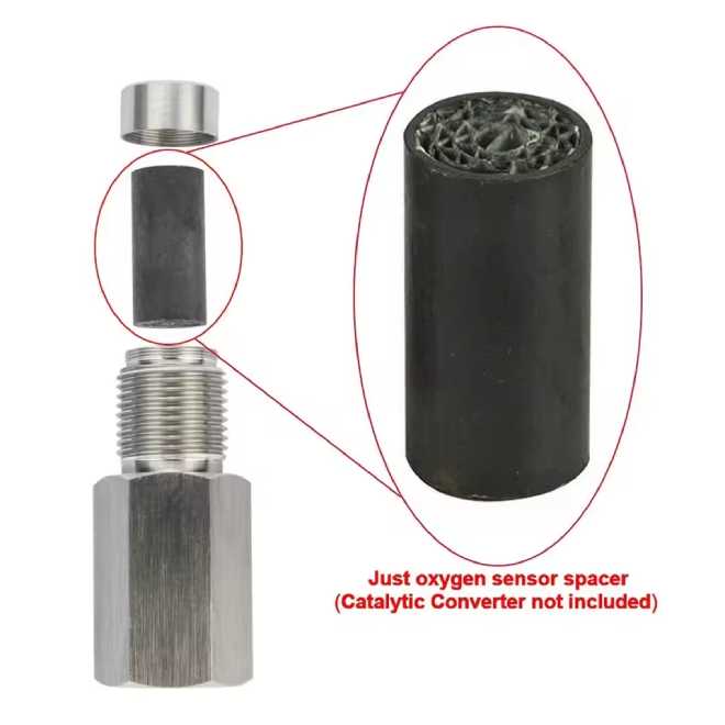
To pass complex ECM monitoring without triggering response-time errors, advanced spacers integrate a miniature ceramic or metallic 400 CPSI catalytic core inside the M18x1.5 body. This micro-substrate is coated with precious metals (Platinum, Palladium, and Rhodium). As a small gas sample enters the spacer chamber, the mini-cat core chemically oxidizes unburned hydrocarbons (HC) and carbon monoxide (CO) directly on the sensor tip, maintaining realistic oxygen consumption rates without starving the sensor.
Chinese manufacturers specializing in exhaust aftermarket parts commonly adopt standardized sintering and coating processes for mini-cat cores, ensuring stable catalytic activity that matches mainstream ECU signal recognition standards.
How to Choose the Right O2 Sensor Spacer Design for Your Exhaust Space
|
Spacer Type
|
Physical Clearance
|
Flow Restriction Strategy
|
Recommended Application
|
|---|---|---|---|
|
Straight Mini-Cat Spacer
|
Requires ~2.5 inches of radial clearance around bung.
|
Integrated 400 CPSI Micro-Catalytic Core.
|
High-flow catalytic converters, aftermarket downpipes with direct inline bungs.
|
|
90-Degree Modular Elbow Spacer
|
Requires < 1.5 inches of tight transmission tunnel clearance.
|
90° Directional Change + Calibrated Chamber.
|
AWD vehicles, tight Euro downpipes, low-clearance chassis tunnels.
|
|
Adjustable Flow Jet Insert Spacer
|
Variable inline clearance required.
|
Interchangeable Restrictor Jets (1.5mm, 2.5mm, 4.0mm).
|
Track/Race headers, vehicles with hyper-sensitive secondary fuel trim logic.
|
Adjustable and elbow-style spacers are widely produced in Chinese facilities with CNC precision machining, supporting compatible sizing for most U.S. and European imported vehicles.
Will Installing an O2 Sensor Spacer Affect Your Engine's Fuel Trims?
A common misconception among automotive enthusiasts is that placing a spacer on the downstream oxygen sensor will cause the engine to run dangerously lean or rich.
Primary vs. Secondary Fuel Trims Explained
Primary Control (Upstream - Sensor 1): Modern engine management relies 100% on Sensor 1 to calculate short-term fuel trim (STFT) and long-term fuel trim (LTFT). Spacers are NEVER installed on Sensor 1.
Secondary Fuel Trims (Downstream - Sensor 2): Certain high-performance factory ECU tunes (such as late-model BMW DME, Audi Simos, and Subaru Denso) utilize secondary fuel trim corrections. In these specific systems, if Sensor 2 detects prolonged rich or lean bias, it makes minor fine-tuning adjustments (+/- 2% to 5%) to primary fueling.
Expert Engineering Tip: When using a quality mini-catalytic converter spacer on Sensor 2, the smoothed 0.65V signal sits precisely in the target window expected by the ECM. This prevents the ECU from applying unwanted secondary fuel trim compensations, ensuring optimal air-fuel ratios under both cruise and wide-open throttle (WOT) conditions.
Step-by-Step Diagnostic Benchmarking: How to Verify Spacer Functionality with an OBD-II Scanner
After installing an O2 sensor spacer, do not simply clear codes and drive away. Use a live-data OBD-II diagnostic tool (such as VCDS, FORScan, or Autel) to verify signal accuracy:
Warm Up the Engine: Drive the vehicle until the engine reaches operating temperature (85°C - 95°C) and enters Closed-Loop Mode.
Select Live Data Channels: Graph Upstream O2 Sensor Voltage (Bank 1 Sensor 1) alongside Downstream O2 Sensor Voltage (Bank 1 Sensor 2).
Execute Steady Cruise Test: Maintain vehicle speed at 55 mph (90 km/h) on a flat highway with constant throttle position.
Evaluate Waveform Graph:
Upstream Waveform: Should cycle rapidly between 0.1V and 0.9V.
Downstream Waveform (With Correct Spacer): Should display a clean, stable line between 0.60V and 0.75V with minimal oscillation.
Frequently Asked Questions (FAQ)
1. Will an O2 sensor spacer allow my vehicle to pass official state emission inspections?
An O2 sensor spacer can allow the ECU's onboard diagnostic monitors to complete self-tests and display an "OBD Ready" status on standard scan tools. However, vehicle owners must check local and federal environmental laws (such as EPA or CARB regulations). In many jurisdictions, installing spacers or altering emission control equipment on public highways is strictly prohibited and intended for off-road or motorsport use only.
2. What thread pitch specification is required for an O2 sensor spacer?
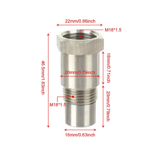
Over 98% of modern passenger vehicles use standard oxygen sensors with an M18x1.5mm thread pitch. Always ensure the spacer is CNC-machined from 304 stainless steel or nickel-plated steel to prevent thread galling, oxidation, and sensor seizure under extreme exhaust gas temperatures (700°C+).
Most Chinese manufacturers producing these parts adopt unified thread standard calibration, ensuring interchangeability and compatibility with mainstream U.S. market vehicle specifications.
3. Should anti-seize compound be used during installation?
Yes. Apply a high-temperature copper or nickel-based anti-seize compound sparingly to the male threads of the spacer. Ensure that no anti-seize contacts the internal sensor tip or mini-catalyst core, as metallic compounds will permanently poison the sensor membrane.
Leave a Reply