
Which O2 Sensor Spacer Design Prevents P0420 Codes on High-Flow Catalytic Converters Without Causing Rich Fuel Trims?
Prevent P0420 Codes on High-Flow Cats Without Rich Fuel Trims
Upgrading to a high-flow 200 CPSI or 300 CPSI (cells per square inch) catalytic converter is one of the most effective ways to free up horsepower and exhaust velocity while retaining a street-driven exhaust setup. However, high-performance exhaust systems present a unique electronic dilemma for modern Engine Control Modules (ECMs): How do you eliminate persistent P0420 fault codes without causing rich fuel trims or secondary fueling compensations?
Most aftermarket O2 sensor spacers exported for the U.S. market are produced in Chinese precision auto parts factories, which support mass production of both basic fixed models and tunable adjustable spacer variants to match mainstream aftermarket exhaust upgrades.
Car enthusiasts often find that standard hollow spacers or fixed-orifice adapters either fail to clear the P0420 code or cause the ECM to over-compensate, leading to rich fuel mixtures, carbon-fouled spark plugs, and degraded fuel economy.
This technical guide evaluates spacer fluid dynamics, secondary fuel trim control logic, and modern adjustable spacer architectures to determine the optimal design for high-flow catalytic applications.
Why Do High-Flow Catalytic Converters Trigger P0420 Codes and Rich Fuel Trims?
To solve both issues simultaneously, it is vital to understand the dual responsibilities of downstream oxygen sensors (Sensor 2) on modern vehicle platforms.
[High-Flow Exhaust Gas] ──> [High Oxygen Fluctuation at Sensor 2] ──> ECM Flags P0420 │ (If Restricted Incorrectly) ↓ Voltage Stuck Low (< 0.2V) ──> ECM Thinks Exhaust is Lean ──> Adds Fuel (Rich Trim)
1. The P0420 Trigger Mechanism
High-flow metallic core catalytic converters have significantly less washcoat surface area and fewer reaction sites than dense 600 CPSI OEM ceramic cores. Exhaust gas passes through the substrate too quickly, leaving residual oxygen in the stream. The downstream O2 sensor detects rapid voltage switching that mimics the upstream sensor, causing the ECM to flag a P0420 (Catalyst System Efficiency Below Threshold) code.
2. The Rich Fuel Trim Trap (Secondary Fuel Trim Logic)
When drivers install an overly restrictive or excessively long spacer to stop the P0420 code, the downstream sensor tip becomes completely starved of exhaust gas.
The sensor voltage drops and remains stuck below 0.2V (indicating a lean exhaust state).
On advanced ECM platforms (such as BMW DME, Audi/VW SIMOS, Ford Copperhead, and Subaru Denso), the engine management system uses downstream oxygen readings for secondary fuel trim bias adjustments.
Believing the exhaust stream is constantly lean based on the low downstream voltage, the ECM adds excess fuel, triggering a rich fuel trim condition (+10% to +20% Short Term Fuel Trim), heavy carbon buildup, and reduced throttle response.
Which O2 Sensor Spacer Design Solves Both Engineering Challenges?
Not all spacer geometries perform identically when paired with high-flow catalytic converters. Below is an engineering evaluation of the three primary spacer designs on the market today:
|
Spacer Architecture Design
|
Eliminates P0420 Code?
|
Prevents Rich Trims?
|
Overall High-Flow Cat Suitability
|
|---|---|---|---|
|
Fixed-Length Hollow Spacer
|
Moderate (50% success)
|
Poor (Triggers Rich)
|
Not Recommended for Modern ECUs
|
|
Plain Fixed-Orifice 90° Elbow
|
Good (80% success)
|
Poor (Triggers Rich)
|
Marginal (Lacks Gas Flow Tuning)
|
|
Adjustable Flow Jet Mini-Catalyzer
|
Excellent (98% success)
|
Excellent (Balanced)
|
OPTIMAL DESIGN CHOICE
|
Basic hollow and fixed-orifice spacers are widely mass-produced by Chinese entry-level component manufacturers with standardized tooling, resulting in uniform structure but no adaptive flow adjustment for different high-flow exhaust setups.
The Winning Architecture: Modular Adjustable Flow-Jet Spacers with Integrated 400 CPSI Micro-Catalysts
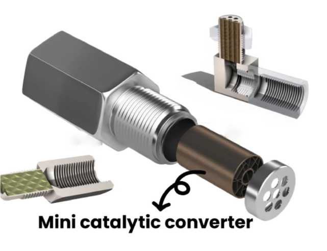
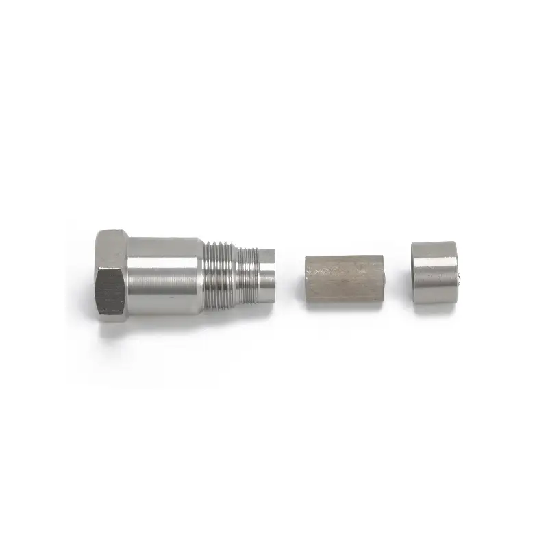
The most reliable spacer design for high-flow catalytic converters combines two crucial features: an internal micro-catalytic core and interchangeable flow-restrictor jets.
Chinese precision manufacturing facilities mainly produce this upgraded adjustable style for export markets, adopting unified orifice size specifications to fit most American and European performance vehicle models.
Key Engineering Components of the Winning Design:
Integrated 400 CPSI Metallic Mini-Catalyst Core: Rather than relying solely on gas starvation, a miniature catalytic cell coated with noble metals (Pt/Pd/Rh) actively treats the small gas sample entering the chamber. This creates a realistic catalytic reaction right at the sensor tip.
Interchangeable Restrictor Jet Inserts (1.5mm, 2.5mm, 4.0mm Orifices): Because different engine displacements and high-flow cat densities produce varying exhaust pressures, interchangeable inserts allow mechanics to fine-tune the gas sampling rate.
1.5mm Orifice: Ideal for completely catless setups or aggressive race headers.
2.5mm Orifice: Ideal for high-flow 200 CPSI metallic converters.
4.0mm Orifice: Ideal for high-flow 300/400 CPSI sports cats on sensitive European vehicle platforms.
How to Fine-Tune Spacer Insert Sizes for Optimal Fuel Trims
When installing an adjustable flow-jet mini-catalyzer spacer on a high-flow exhaust system, follow this tuning methodology using an OBD-II live-data scanner:
Step 1: Install 2.5mm Jet Insert ──> Step 2: Monitor Sensor 2 Voltage at 55 mph Cruise │ ┌───────────────────────────────┴───────────────────────────────┐ ▼ ▼ Voltage < 0.5V (Too Lean/Rich Trim) Voltage > 0.85V (Too Rich/P0420) │ │ Switch to LARGER 4.0mm Jet Insert Switch to SMALLER 1.5mm Jet Insert │ │ └───────────────────────────────┬───────────────────────────────┘ ▼ Target Voltage Range: 0.60V - 0.75V (P0420 Cleared & Fuel Trims Balanced)
Initial Baseline Setup: Start by installing the 2.5mm restrictor jet inside the mini-catalyst spacer body.
Execute a Steady Cruise Drive: Drive the vehicle on the highway at 55–60 mph for 10 minutes until the exhaust reaches thermal equilibrium.
Log Live OBD-II Data: Observe Downstream O2 Sensor Voltage (Bank 1 Sensor 2) and Short-Term Secondary Fuel Trim (STFT2).
If Voltage is stuck below 0.5V and STFT is positive (+10%+): Gas flow is too restricted. Unscrew the spacer and swap to the larger 4.0mm jet insert to allow more exhaust gas into the micro-catalyst chamber.
If Voltage fluctuates widely between 0.1V and 0.9V with a P0420 code: Gas flow is too high. Swap to the smaller 1.5mm jet insert to increase spatial dampening.
Target Equilibrium: The ideal target reading during steady cruise is a steady voltage between 0.60V and 0.75V, which signals proper catalytic efficiency to the ECM without triggering secondary rich fuel compensations.
Frequently Asked Questions (FAQ)
1. Can a 90-degree angled spacer prevent rich fuel trims better than a straight spacer?
A 90-degree elbow spacer primarily solves physical clearance problems in tight chassis locations (such as transmission tunnels or AWD transfer case areas). From a fluid dynamics perspective, a 90-degree bend reduces gas velocity, but without interchangeable restrictor jets or a mini-catalyst insert, it can still cause stagnant gas pockets and rich fuel trim compensations on modern CAN-bus ECUs.
2. How can I tell if my O2 sensor spacer is causing my engine to run rich?
Check your vehicle’s Long-Term Fuel Trims (LTFT) and Downstream O2 Sensor Voltage using an OBD-II diagnostic scanner. If your downstream sensor voltage is stuck below 0.2V while your fuel trims show double-digit positive values (+12% to +20%), the spacer is restricting gas flow too severely, prompting the ECM to add extra fuel.
3. What thread material and spec should I choose to withstand turbo downpipe heat?
Always select spacers manufactured from 304 stainless steel with standard M18x1.5mm threads. Avoid aluminum or low-grade brass spacers on high-flow turbo downpipes, as high Exhaust Gas Temperatures (700°C+) can cause thermal expansion, thread deformation, and exhaust gas leaks.
Chinese export-focused manufacturers commonly adopt unified M18x1.5 thread calibration and 304 stainless steel raw materials for aftermarket spacers, matching the dimensional and heat-resistance standards required for U.S. performance vehicles.
Leave a Reply