

As a technician with years of automotive repair experience, I've found that faulty oxygen sensors are a common cause of abnormal fuel consumption and emissions issues. How Oxygen Sensors Work and How to Test Replacement Oxygen Sensors. Based on actual test data, a malfunctioning oxygen sensor can increase fuel consumption by over 15%. This article will analyze the working principles and testing methods of this critical component, drawing from professional technical manuals and repair case studies.
Automotive Sensor Series: How Oxygen Sensors Work
When your check engine light illuminates, have you ever considered that this small component might be the primary culprit? As a critical monitoring point in the vehicle's emission system, a malfunctioning oxygen sensor can cause fuel consumption to surge by over 15% and triple exhaust pollutant emissions. This article provides a comprehensive analysis of this environmental component installed on the exhaust pipe, covering its mounting location, internal structure, and diagnostic and repair methods.
Front and Rear Oxygen Sensors: A Critical Pair in the Exhaust System.
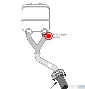
Lift the hood and follow the exhaust pipe. Between the exhaust manifold and the catalytic converter, you'll find the first metal component with wires—this is the front oxygen sensor. It acts like a monitoring probe at the exhaust outlet, directly detecting the oxygen content in the exhaust gases after combustion. It sends this data in real time to the ECU to adjust fuel injection. The rear oxygen sensor, positioned behind the catalytic converter, continuously monitors the condition of the purified exhaust gases. By comparing data from both sensors, it determines whether the catalytic converter is functioning properly.

The front oxygen sensor's installation location subjects it to exhaust gas temperatures exceeding 600 degrees Celsius, necessitating the use of high-temperature-resistant zirconia ceramic material. While the rear oxygen sensor operates at slightly lower temperatures, it must also withstand damage from corrosive gases. These two monitoring units have distinct responsibilities: the front sensor handles closed-loop control of the air-fuel ratio, while the rear sensor focuses on monitoring the efficiency of the three-way catalytic converter. Together, they ensure efficient engine combustion and clean exhaust emissions.
Internal Structure of Oxygen Sensors: From Ceramic Tubes to Heating Coils
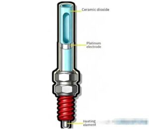
Removing the metal housing reveals a core component: a porous zirconia ceramic tube coated with platinum electrodes on both inner and outer surfaces. This seemingly simple design incorporates sophisticated electrochemical principles—at high temperatures, the ceramic tube transforms into an oxygen ion conductor. When oxygen concentrations on either side differ, it generates a millivolt-level voltage difference. To enable rapid sensor activation (typically requiring temperatures above 300°C), modern oxygen sensors incorporate built-in heating coils. This heating mechanism functions as a built-in heater for the ceramic tube, capable of raising temperatures to 600°C within 30 seconds during cold starts.
In addition to mainstream zirconia-type sensors, some vehicles also utilize titania-type sensors. At its core lies a thick-film titanium dioxide element that detects oxygen concentration through resistance changes—resistance increases when exhaust oxygen content is high and decreases otherwise. This sensor features a simpler construction and lower cost but requires additional temperature compensation circuitry.

Principle of Voltage Change: How Oxygen Sensors Interpret Exhaust
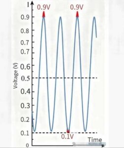
When the fuel mixture is too rich (air-fuel ratio below 14.7), oxygen levels in the exhaust are extremely low. This creates a significant concentration difference inside and outside the zirconia tube, causing the sensor to output a high voltage of 0.8-1.0 volts. Conversely, when the mixture is too lean (air-fuel ratio above 14.7), ample oxygen in the exhaust causes the voltage to drop sharply to 0.1-0.3 volts. This voltage signal fluctuating around a 0.45-volt baseline acts as the sensor's communication to the ECU: “The mixture is currently too rich—reduce fuel injection!” or “It's now too lean—increase fuel injection!”
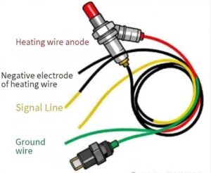
The wideband oxygen sensor represents a further advancement. By actively regulating the oxygen concentration in the measurement chamber via an internal “oxygen pump,” it can output a linear signal across a broad air-fuel ratio range of 10 to 20. Among its six leads, besides the heating wire and signal wire, it includes an oxygen pump current control wire. This effectively adds performance-enhancing functionality to the sensor, achieving air-fuel ratio control accuracy to within ±0.3.

How to Test Replacement Oxygen Sensors
Multimeter Practical Operation: Three-Step Diagnosis of Oxygen Sensor Status
Step 1: Heating Resistance Check
Disconnect the oxygen sensor connector. Use a multimeter to measure the resistance between the heating terminals (typically 4-40 ohms). For common four-wire narrowband sensors, the two white wires are the heating wires. If the resistance reads infinite or near zero ohms at room temperature, it indicates a broken or shorted heating wire.
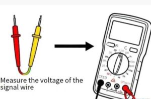
Step 2: Signal Voltage Measurement
Start the engine and allow it to reach operating temperature. Measure the signal pin using the multimeter's DC voltage setting. Under normal conditions, the voltage should rapidly fluctuate between 0.1-0.9 volts, changing at least eight times within ten seconds. If the voltage remains fixed at 0.45 volts or 0/1 volt, the sensor has failed.
Step 3: Dynamic Response Test
Suddenly depress the accelerator pedal and release it. Observe the voltage change: During rapid acceleration, the fuel mixture enriches, and the voltage should immediately rise above 0.8 volts. When releasing the accelerator, the mixture leans out, and the voltage should drop below 0.2 volts. A sluggish response indicates sensor aging.
Data Stream Interpretation: Assessing Engine Condition Through Voltage Fluctuations
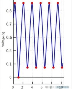
When connected to an OBD diagnostic tool, you will observe the oxygen sensor data stream displaying characteristic waveforms. A normal front oxygen sensor waveform exhibits sawtooth-like fluctuations, with an amplitude ranging from 0.8 to 0.9 volts and a frequency exceeding 0.5 hertz. The rear oxygen sensor waveform, in contrast, appears relatively stable with smaller fluctuations. When upstream and downstream sensor waveforms become similar, it indicates the three-way catalytic converter has failed and requires replacement.
Healthy Data Stream Reference:
Front Oxygen Sensor: 0.1-0.9 volt fluctuations, 8-10 changes within 10 seconds
Rear Oxygen Sensor: 0.3-0.7 volt fluctuations, amplitude 50% smaller than front sensor
Long-Term Fuel Correction: Within +5%
Common Failures: Carbon Deposits, Chemical Poisoning, and Wiring Issues
The most frequent issues with oxygen sensors include carbon buildup. Prolonged short-distance driving causes incomplete combustion, where carbon particles clog the sensor's porous ceramic body, resulting in weakened signal voltage fluctuations.

More severe is chemical poisoning:
Lead poisoning: Using leaded gasoline causes platinum electrode failure, resulting in a reddish-brown top on the sensor.
Silicon poisoning: Using silicone sealant during repairs forms silica crystals at high temperatures.
Sulfur poisoning: Sulfur in low-quality fuel creates a sulfide coating.
In these cases, the sensor must be replaced. Comparing new and old sensors reveals a distinct color abnormality on the top of the failed sensor.
Closed-Loop Control: How Oxygen Sensors Help Save Fuel
When oxygen sensors work in tandem with the ECU, they establish a sophisticated closed-loop control system. The ECU adjusts fuel injection based on pre-oxygen sensor signals to maintain the ideal air-fuel ratio of 14.7:1. At this ratio, the three-way catalytic converter achieves maximum efficiency in converting carbon monoxide, hydrocarbons, and nitrogen oxides. This process undergoes over ten adjustments per second, providing precise engine management. Compared to open-loop control, it reduces fuel consumption by 10%-15%.

Summary: Three Key Points for Oxygen Sensor Maintenance
Use High-Quality Fuel: Gasoline with excessive sulfur content can cause sensor poisoning and failure.
Regularly Check Waveforms: During maintenance, use a diagnostic tool to monitor signal changes and identify signs of aging early.
Proper Replacement and Installation: Always perform when cool, apply anti-seize compound, and secure to the specified torque
This small component hidden in the exhaust system is both a crucial part of environmental protection and a key player in fuel efficiency. Understanding its operation not only helps save repair costs but also provides insight into your vehicle's health. Next time the check engine light illuminates, try inspecting the oxygen sensor first—this simple step could save you thousands in repair bills.
For routine testing to verify oxygen sensor condition, use the 02 Oxygen Sensor Spacer or 90-Degree O2 Sensor Spacer.
Following the three maintenance points outlined in this article can effectively extend the lifespan of your oxygen sensors. For additional automotive repair guidance, we recommend consulting a certified repair facility. Feel free to share your vehicle maintenance experiences in the comments section—we'll provide expert answers to your questions.
Leave a Reply